
Automated Deployable Cup Holder System
Designed an automated retractable cup holder for compact integration and responsive user interaction
Combined mechanical actuation, sensing, and control into a single functional prototype
Developed the system to detect user input and trigger controlled deployment behavior
Focused on compact packaging, repeatable motion, and ease of integration into an enclosed product environment
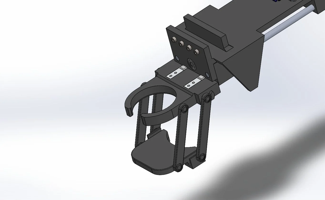
The mechanism is built around a four-bar linkage, enabling a foldable bottom support that allows the cup holder to retract into a compact form when not in use.
Actuation is provided by a lead screw mechanism, which drives controlled linear motion and translates it into the deployment and retraction of the linkage.
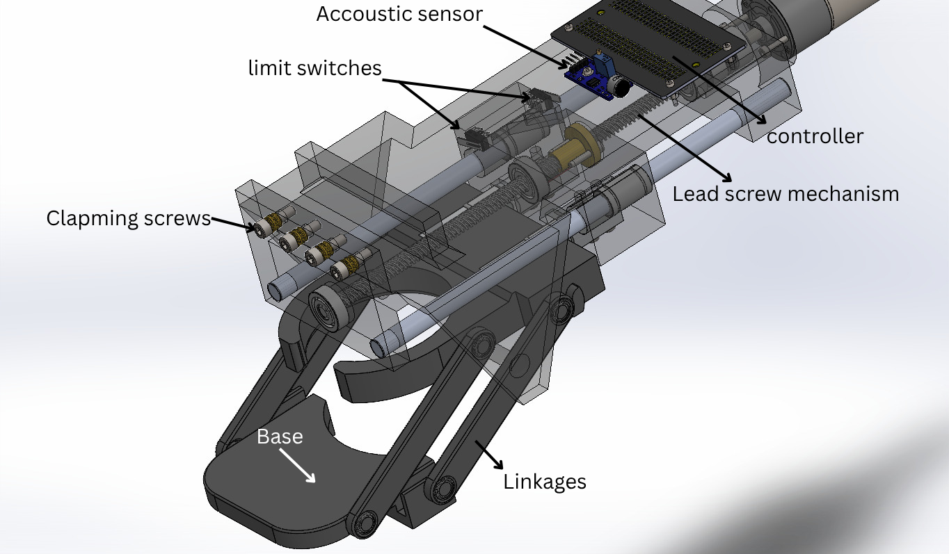
The system integrates multiple sensing and control elements:
Two limit switches for end-of-travel detection and motor protection
Two 1 kg load cells, which serve both as sensing elements and primary structural supports
An acoustic sensor module for user-triggered interaction
An ESP32 microcontroller to coordinate sensing, control logic, and actuation
The entire assembly is mounted beneath a desk on a 2.5 × 2.5 cm support beam, with the base secured via four M5 fasteners, providing enough clamping force to support the rigid installation including the drink.
A fully functional prototype was built, integrating the four-bar linkage, lead screw actuation, and sensing system into a compact assembly. The mechanism was tested through repeated deployment cycles to evaluate consistency and reliability. Throughout testing, all sensors—including load cells, limit switches, and the acoustic module—were verified to operate seamlessly within the controller logic, enabling coordinated and responsive system behavior.
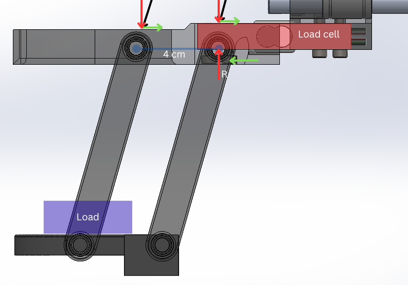
The top linkage was analyzed using a simplified free-body diagram, modeling the angled links as force-transmitting members. For a centered load and symmetric setup, the vertical force is shared between both sides, so the load cell measures roughly half of the total load:
R≈L/2
This gives a theoretical maximum load of about 4 kg for a 2 kg load cell. The link angle affects the internal forces within the members, but not the overall load split.
In practice, the system is operated well below this limit due to the use of 3D printed components, which have lower strength and stiffness.